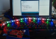
Arduino and WS2801 RGB LED strip
29.9.2011
Recently, i ordered a sample of a ws2801 based RGB LED strip from China. After todays successful playing around with it, I plan to order a bigger quantity beginning of next week.
RGB strips contain a number of individually addressable RGB LEDs - in this instance 32 per meter. Each RGB pixel has its own tiny controller to control its color. The color is quite bright, green and red almost hurt my eyes at the maximum brightness. White has some blueish-violet quality, which makes it look interesting but its not perfect white (i read for that you would want LEDs with an additional 4th white LED which my strips seem not to have). The WS2801 protocol sounds simple, but instead of implementing it, i just took the library fastspi for the arduino SPI component. The code for the
The hard part was figuring out which cable fits into which pin of my Seeeduino (Arduino clone). There is something printed on the strip, but the names do not all match the documentation. And the manufacturer of the strips got the coloring scheme of the cables rather weird, use a non-standard byte order for colors and the sample code did not work out of the box. Luckily i figured it out with reading some of the Arduino spec and have the info gathered here for reference (Warning: The cable colors seem to be random, not all of my strips have the same color for the same thing):
Note that SPI knows two more pins, SS and MISO, to switch communication from slave devices to master and receive data from slaves, but the strips have no cable for that and its not needed as there is nothing to read from the strips.
The color order i had to use with fastspi was
I had to manually set the SPI DataRate to 2, below 2 i get lots of weird flickering. fastspi claims to set the data rate based on the chipset but either my WS2801 are not original or otherwise flawed or something is wrong with the library. Whatever, you can do
Thats it for now, but stay tuned for more once i get longer strips of LEDs :-)
RGB strips contain a number of individually addressable RGB LEDs - in this instance 32 per meter. Each RGB pixel has its own tiny controller to control its color. The color is quite bright, green and red almost hurt my eyes at the maximum brightness. White has some blueish-violet quality, which makes it look interesting but its not perfect white (i read for that you would want LEDs with an additional 4th white LED which my strips seem not to have). The WS2801 protocol sounds simple, but instead of implementing it, i just took the library fastspi for the arduino SPI component. The code for the
loop() function to produce "walking" red, green and blue dots looks like the following (plus some initialization as found in the sample of fastspi):
// walking r-g-b

for (int j = 0; j < 3; j++) {

    memset(leds, 0, NUM_LEDS * 3);

    for(int i = 0; i < NUM_LEDS; i++ ) {

        switch((i+j) % 3) {

        case 0: leds[i].r = 200; break;

        case 1: leds[i].g = 200; break;

        case 2: leds[i].b = 200; break;

    }

}

FastSPI_LED.show();

delay(300);
The hard part was figuring out which cable fits into which pin of my Seeeduino (Arduino clone). There is something printed on the strip, but the names do not all match the documentation. And the manufacturer of the strips got the coloring scheme of the cables rather weird, use a non-standard byte order for colors and the sample code did not work out of the box. Luckily i figured it out with reading some of the Arduino spec and have the info gathered here for reference (Warning: The cable colors seem to be random, not all of my strips have the same color for the same thing):
- 5V = + 5 volts
- CK = SPI clock, pin 13
- SD = SPI data (master to slave, MOSI), pin 11
- GND = Ground
Note that SPI knows two more pins, SS and MISO, to switch communication from slave devices to master and receive data from slaves, but the strips have no cable for that and its not needed as there is nothing to read from the strips.
The color order i had to use with fastspi was
struct CRGB { unsigned char b; unsigned char g; unsigned char r; };. (You can easily try this out without any danger of breaking something, just set one field to 255 and the others to 0. Whatever that color is is in that field and can be named accordingly.I had to manually set the SPI DataRate to 2, below 2 i get lots of weird flickering. fastspi claims to set the data rate based on the chipset but either my WS2801 are not original or otherwise flawed or something is wrong with the library. Whatever, you can do
FastSPI_LED.setDataRate(2);. To figure out your value, start with rate of 7 (slowest) and lower down to 0 until you get flickers when adressing all LEDs.Thats it for now, but stay tuned for more once i get longer strips of LEDs :-)

